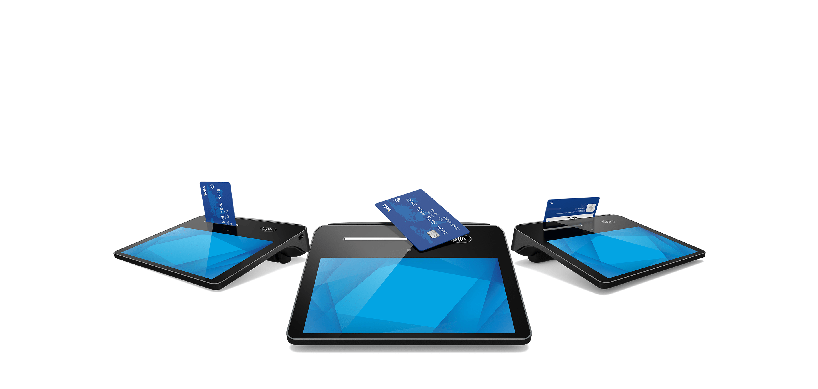
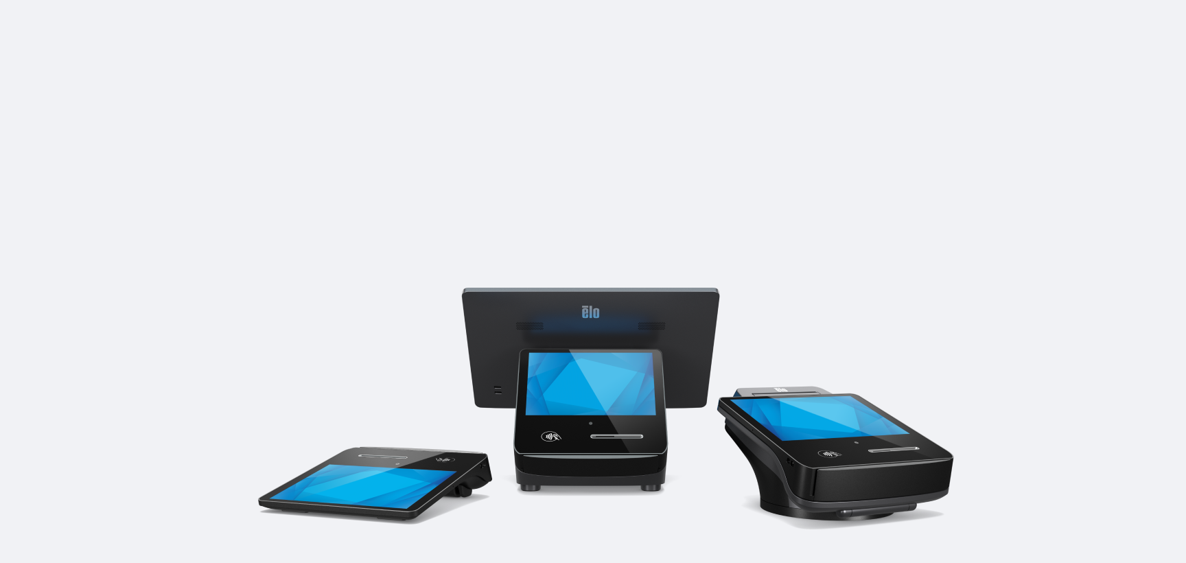
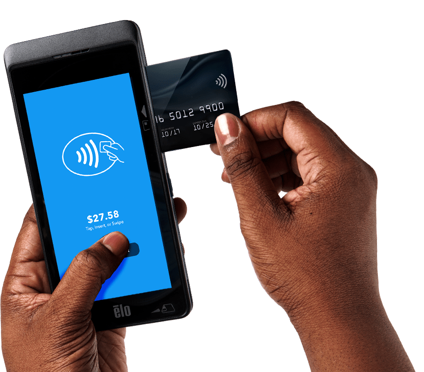
A game changer
for payments.
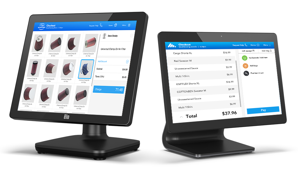
Quick ship Intel products.
Elo’s Quick Ship program expedites customer deliveries of
select Intel-based touchscreen computers.

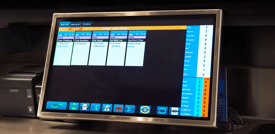
Kitchen automation
you can count on.
Increase efficiency and reduce bottlenecks with Elo’s line of Kitchen Display Systems.
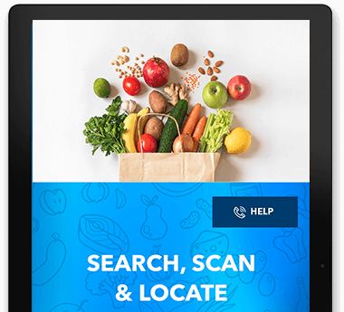
Interactive solutions for grocery stores.
Enhance the grocery shopping experience, increase customer engagement, enable self-service and promote brand loyalty with modular touchscreen solutions.
Manage your devices
easily with EloView®
EloView allows you to deploy and securely manage your entire network of Android-powered Elo devices from anywhere in the world.
Enhance patient care
where it matters.
Streamline your healthcare administration and enhance the patient experience.
Mobility built
for enterprise.
Android mobile computers designed to support your everyday business.

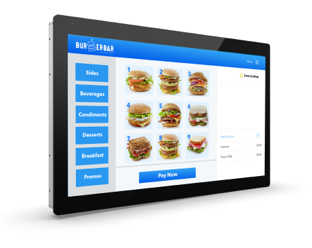
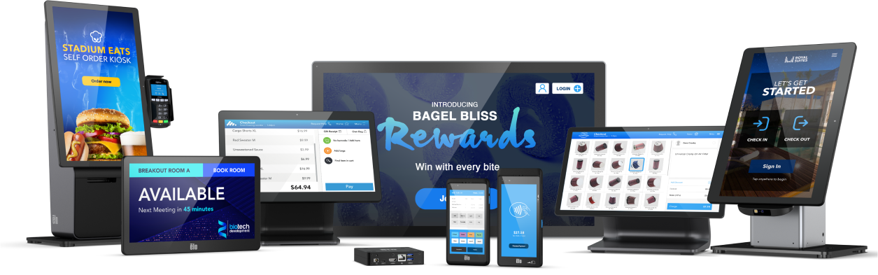
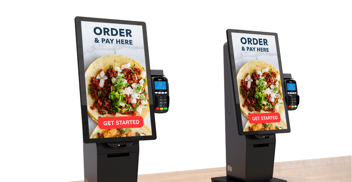
Self-service
solutions made easy.
Versatile self-service platform designed to adapt to consumers’ changing behavior.
Outdoor
Open Frames
Designed to survive the elements, Elo's weatherproof touchscreen covers you from day to night.