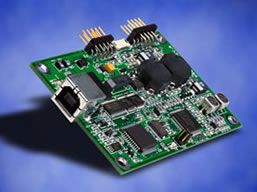
2500Sz Serial Controller (Discontinued November 2005)
Specifications
-
Technical
Part Number(s)
F20786-000
Technology
5-Wire Resistive (AccuTouch®)
Dimensions
2.36" x 3.30" x 0.40" / 59.94 mm x 83.82 mm x 10.16 mm
Interface
EIA 232E (Serial RS-232), DCE configuration. 8 Data Bits, 1 Stop Bit, No Parity, Full Duplex
DSR is pulled HIGH (>+3V) by the 2500Sz when powered. DTR can be asserted to interrupt the flow of data from the controllerResolution
4096x4096, size independent, 255 levels of Z (pressure)
Conversion Time
Approximately 10.4 ms per coordinate set
Power
+5 VDC, nominal (+4.75V to +5.25V) or +12VDC, nominal (+10.8V to +13.2V)
Input Voltage
+4.75V to +5.25V
Baud Rate
9600 (default) and 19200
Reliability
MTBF greater than 300,000 hours per MIL-HDBK-217-F2 using the parts stress calculation method for ground benign environment with an ambient temperature of 25°C
Construction
Four-layer surface-mount design with internal ground plane for EMI suppression
Flammability
The printed circuit board substrate is rated 94V0. All plastic components, such as headers and connectors, are also rated 94V0.
Shock and Vibration
Three axis sine wave, 50 Hz to 2kHz, 1 G, 2 minutes/Octave with dwell on resonances
ESD
Per EN 6100-4-2 1995: Level 4. Contact discharge 8kV, air discharge 15kV.
LED Diagnostic Characteristics
A green LED indicates controller status as follows:
LED Blink Rate: Once per second
Function: Normal condition, untouched state
LED Blink Rate: On continuously
Function: Touched state
LED Blink Rate: Twice per second
Function: Error detectedJumpers
The 2500Sz is shipped with a single jumper fitted to not enable either J1 or J2. Consult the drawings later in this document for the position of the jumpers.
Jumper: J1
Function: Set NVRAM to defaults on power up
Jumper: J2
Function: Emulation Mode = E281A-4002Current - Operating Mode
Full IntelliTouch SmartSet or E281A-4002 protocols, jumper selectable
Initial/ Stream/ Untouch/ Z-axis Enable ModesOperating Temperature
0°C to 65°C
Storage Temperature
-25°C to 85°C
Humidity
Operating: 10% to 90% RH, noncondensing
Storage: 10% to 90% RH, noncondensingAltitude
10,000 feet
MTBF
30,000 hours demonstrated
Regulatory approvals and declarations
Elo controllers are "CNR/USR" UL Recognized Components for USA and Canada, Category NWGQ2, Information Technology Equipment Including Business Equipment.
Elo controllers are TUV Bauart certified as components.
Elo controllers have been tested for compliance with FCC Part 15 Class B limits.
Depending on the application, it may be necessary to pay special attention to system grounding and shielding, and it may be necessary to apply ferrite suppressor beads.Mounting Options
All mounting holes are plated through for chassis ground connection
Connectors and Pin Definitions
The connector configuration permits the controller to be placed in-line between the touchscreen and serial I/O attachments
Power connector - dual row by five-position header with 0.025-inch pins on 0.100 centers. The header is compatible with insulation displacement cable (IDC) connectors such as Berg series 71600, series 71602, series 66900, and series 66902, Molex style 40312, Amp series 746285 and series 746288 receptacles. The header is also compatible with crimp termination, discrete wire receptacles and housings including Berg Mini-Latch housings and Mini-PV receptacles, Molex series 70450 connectors, and the Amp AMPMODU Mod. IV connector family. Pin numbering schemes for discrete wire connectors differ between manufacturers.
Touchscreen connector - dual row by six position header with 0.025 inch square pins spaced on 0.100 centers. P3 mates with the Berg Mini-Latch receptacle on the IntelliTouch touchscreen cable. The withdrawal force exceeds 3.9 lbs.
Serial connector and signal descriptions - dual row by five position header with 0.025 inch pins on 0.100 centers. The header is compatible with insulation displacement cable (IDC) connectors such as Berg series 71600, series 71602, series 66900, and series 66902, Molex style 40312, Amp series 746285 and series 746288 receptacles. The header is also compatible with crimp termination, discrete wire receptacles and housings including Berg Mini-Latch housings and Mini-PV receptacles, Molex series 70450 connectors, and the Amp AMPMODU Mod. IV connector family. Pin numbering schemes for discrete wire connectors differ between manufacturers. When the mating IDC receptacle is cabled to an IDC DB-9 connector, the interface assumes a DCE configuration as described in ANSI/EIA/TIA 232-E.Optional Software/Hardware Handshaking
RTS/CTS
